- 您现在的位置:买卖IC网 > Sheet目录2000 > IDT5T940-10NLGI (IDT, Integrated Device Technology Inc)IC CLK GENERATOR PREC 28-VFQFPN
6
INDUSTRIALTEMPERATURERANGE
IDT5T940
PRECISION CLOCKGENERATOROC-192 APPLICATIONS
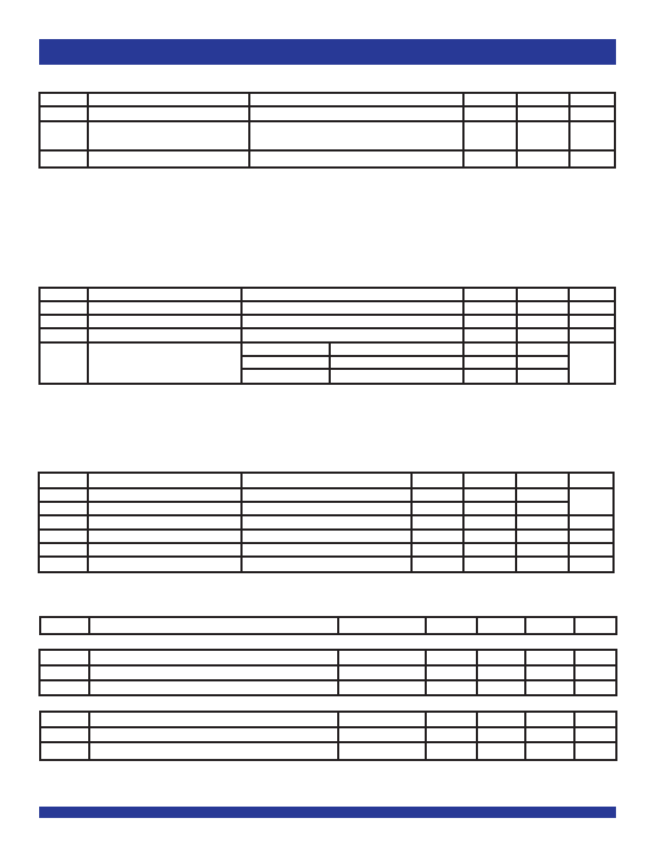
DC ELECTRICAL CHARACTERISTICS OVER OPERATING RANGE FOR LVTTL
Symbol
Parameter
Test Conditions
Min.
Typ.
Max
Unit
IIH
Input HIGH Current
VDD = 3.465V
—
±1
μA
IIL
InputLOWCurrent
VDD = 3.465V
—
±1
VIK
ClampDiodeVoltage
VDD = 2.375V, IIN = -18mA
—
- 0.7
- 1.2
V
VIN
DCInputVoltage
- 0.3
—
+3.465
V
VIH
DC Input HIGH
1.7
—
V
VIL
DC Input LOW
—
0.7
V
DC ELECTRICAL CHARACTERISTICS OVER OPERATING RANGE FOR LVPECL(1)
Symbol
Parameter
Test Conditions
Min.
Typ.
Max.
Unit
InputCharacteristics
IIN
Input Current (CLKIN, REFIN)
VDD = 3.465V
-20
—
+20
μA
VCMR
CommonModeInputVoltage
1
—
VDD - 0.3
V
VDIF
DifferentialVoltageRequiredtoToggleInput
100
——
mV
OutputCharacteristics
VOH
Output Voltage HIGH (terminated through 50
Ω tied to VDD - 2V)(2)
VDD - 1.15
—
VDD - 0.9
V
VOL
OutputVoltageLOW(terminatedthrough50
ΩtiedtoVDD-2V)(2)
VDD - 1.95
—
VDD - 1.61
V
VSWING
Peak-to-PeakOutputVoltageSwing
0.55
—
0.93
V
NOTES:
1. VDD = 2.375 - 3.645V.
2. Not to exceed VDD - 0.05V.
POWER SUPPLY CHARACTERISTICS(1,2)
Symbol
Parameter
Test Conditions
Typ.
Max
Unit
IDD_PD
Power Supply Current
VDD = Max., PD = GND, All outputs unloaded
—
50
μA
ΔIDD
Power Supply Current per Input HIGH
VDD = Max., VIN = 2.375V
—
100
μA
(LVTTLinputsonly)
ITOT
Total Power Supply Current
VDD = Max., QOUT = 622MHz, All outputs unloaded
—
200
mA
NOTES:
1. These power consumption characteristics are for all the valid input interfaces and cover the worst case input and output interface combinations.
2. As a general requirement, these parts must be capable of operating at the maximum frequency under a nominal load at a reasonable operating temperature. That means that
these parts must not burn up under extended use in a typical application.
NOTE:
1. These inputs are normally wired to VDD, GND, or left floating. Internal termination resistors bias unconnected inputs to VDD/2. If these inputs are switched dynamically after powerup,
the function and timing of the outputs may be glitched, and the PLL may require additional tAQ time before all datasheet limits are achieved.
DC ELECTRICAL CHARACTERISTICS OVER OPERATING RANGE
Symbol
Parameter
Test Conditions
Min.
Max
Unit
VIHH
Input HIGH Voltage Level(1)
3-Level Inputs Only
VDD – 0.4
—
V
VIMM
Input MID Voltage Level(1)
3-Level Inputs Only
VDD/2 – 0.2 VDD/2 + 0.2
V
VILL
InputLOWVoltageLevel(1)
3-Level Inputs Only
—
0.4
V
VIN = VDD
HIGH Level
—
200
I3
3-Level Input DC Current
VIN = VDD/2
MID Level
–50
+50
μA
VIN = GND
LOW Level
–200
—
发布紧急采购,3分钟左右您将得到回复。
相关PDF资料
IDT5T9820NLI8
IC CLK DRIVER ZD PLL 68-VFQFPN
IDT5T9890NLI8
IC CLK DRIVER 2.5V PLL 68-VFQFPN
IDT5V19EE604NDGI8
IC PLL CLK GEN 200MHZ 28VFQFPN
IDT5V40501DVG
IC CLK GEN PLL 160MHZ 8TSSOP
IDT5V41064NLGI
IC CLK GEN 1:1 16QFN
IDT5V41066PGG
IC CLK GEN SPRED SPECTRM 20TSSOP
IDT5V49EE901NLGI8
IC PLL CLK GEN 200MHZ 32VFQFN
IDT5V49EE902NLGI
IC CLOCK GEN PLL 500MHZ 32VFQFPN
相关代理商/技术参数
IDT5T940-10NLGI8
功能描述:IC CLK GENERATOR PREC 28-VFQFPN RoHS:是 类别:集成电路 (IC) >> 时钟/计时 - 专用 系列:- 标准包装:1,500 系列:- 类型:时钟缓冲器/驱动器 PLL:是 主要目的:- 输入:- 输出:- 电路数:- 比率 - 输入:输出:- 差分 - 输入:输出:- 频率 - 最大:- 电源电压:3.3V 工作温度:0°C ~ 70°C 安装类型:表面贴装 封装/外壳:28-SSOP(0.209",5.30mm 宽) 供应商设备封装:28-SSOP 包装:带卷 (TR) 其它名称:93786AFT
IDT5T940-30NLGI
功能描述:IC CLK GENERATOR PREC 28-VFQFPN RoHS:是 类别:集成电路 (IC) >> 时钟/计时 - 专用 系列:- 标准包装:1 系列:- 类型:时钟/频率发生器,多路复用器 PLL:是 主要目的:存储器,RDRAM 输入:晶体 输出:LVCMOS 电路数:1 比率 - 输入:输出:1:2 差分 - 输入:输出:无/是 频率 - 最大:400MHz 电源电压:3 V ~ 3.6 V 工作温度:0°C ~ 85°C 安装类型:表面贴装 封装/外壳:16-TSSOP(0.173",4.40mm 宽) 供应商设备封装:16-TSSOP 包装:Digi-Reel® 其它名称:296-6719-6
IDT5T940-30NLGI8
功能描述:IC CLK GENERATOR PREC 28-VFQFPN RoHS:是 类别:集成电路 (IC) >> 时钟/计时 - 专用 系列:- 标准包装:1,500 系列:- 类型:时钟缓冲器/驱动器 PLL:是 主要目的:- 输入:- 输出:- 电路数:- 比率 - 输入:输出:- 差分 - 输入:输出:- 频率 - 最大:- 电源电压:3.3V 工作温度:0°C ~ 70°C 安装类型:表面贴装 封装/外壳:28-SSOP(0.209",5.30mm 宽) 供应商设备封装:28-SSOP 包装:带卷 (TR) 其它名称:93786AFT
IDT5T9820NLGI
功能描述:IC CLK DRIVER ZD PLL 68-VFQFPN RoHS:是 类别:集成电路 (IC) >> 时钟/计时 - 时钟发生器,PLL,频率合成器 系列:- 标准包装:39 系列:- 类型:* PLL:带旁路 输入:时钟 输出:时钟 电路数:1 比率 - 输入:输出:1:10 差分 - 输入:输出:是/是 频率 - 最大:170MHz 除法器/乘法器:无/无 电源电压:2.375 V ~ 3.465 V 工作温度:0°C ~ 70°C 安装类型:* 封装/外壳:* 供应商设备封装:* 包装:*
IDT5T9820NLGI8
功能描述:IC CLK DRIVER ZD PLL 68-VFQFPN RoHS:是 类别:集成电路 (IC) >> 时钟/计时 - 时钟发生器,PLL,频率合成器 系列:- 标准包装:39 系列:- 类型:* PLL:带旁路 输入:时钟 输出:时钟 电路数:1 比率 - 输入:输出:1:10 差分 - 输入:输出:是/是 频率 - 最大:170MHz 除法器/乘法器:无/无 电源电压:2.375 V ~ 3.465 V 工作温度:0°C ~ 70°C 安装类型:* 封装/外壳:* 供应商设备封装:* 包装:*
IDT5T9820NLI
功能描述:IC CLK DRIVER ZD PLL 68-VFQFPN RoHS:否 类别:集成电路 (IC) >> 时钟/计时 - 时钟发生器,PLL,频率合成器 系列:- 标准包装:39 系列:- 类型:* PLL:带旁路 输入:时钟 输出:时钟 电路数:1 比率 - 输入:输出:1:10 差分 - 输入:输出:是/是 频率 - 最大:170MHz 除法器/乘法器:无/无 电源电压:2.375 V ~ 3.465 V 工作温度:0°C ~ 70°C 安装类型:* 封装/外壳:* 供应商设备封装:* 包装:*
IDT5T9820NLI8
功能描述:IC CLK DRIVER ZD PLL 68-VFQFPN RoHS:否 类别:集成电路 (IC) >> 时钟/计时 - 时钟发生器,PLL,频率合成器 系列:- 标准包装:39 系列:- 类型:* PLL:带旁路 输入:时钟 输出:时钟 电路数:1 比率 - 输入:输出:1:10 差分 - 输入:输出:是/是 频率 - 最大:170MHz 除法器/乘法器:无/无 电源电压:2.375 V ~ 3.465 V 工作温度:0°C ~ 70°C 安装类型:* 封装/外壳:* 供应商设备封装:* 包装:*
IDT5T9821NLGI
功能描述:IC CLK DRIVER ZD PLL 68-VFQFPN RoHS:是 类别:集成电路 (IC) >> 时钟/计时 - 时钟发生器,PLL,频率合成器 系列:- 标准包装:39 系列:- 类型:* PLL:带旁路 输入:时钟 输出:时钟 电路数:1 比率 - 输入:输出:1:10 差分 - 输入:输出:是/是 频率 - 最大:170MHz 除法器/乘法器:无/无 电源电压:2.375 V ~ 3.465 V 工作温度:0°C ~ 70°C 安装类型:* 封装/外壳:* 供应商设备封装:* 包装:*